Find us on Google+ Inventor Tales: Search results for 20 sided die
Showing posts sorted by relevance for query 20 sided die. Sort by date Show all posts

Friday, October 26, 2012

All for Fun – Creating a 20 Sided Die

Death and the dice level all distinctions.
Samuel Foote

Many years ago, I friend asked me to create multi-sided die for a website he was creating.  You can still see the images on the banner of the website for DiceHouse Games here.

It was a tricky one to create.  It was a 20 sided die, a much used tool in role playing games like Dungeons and Dragons.

An Autodesk Showcase Rendering of the 20 sided die model

I also used it as an example in a blog post for using the “Change View Orientation”  tool inside of Autodesk Inventor drawings back in February 2012.  

***Edit 13-Nov-2012 : Added an embedded dwf of the 20 sided die***


A 3D dwf of the 20 sided die

*** End Edit***
Since that time I’ve started getting requests for how I built the die, as well as a location to download the actual *.ipt file.  

So here are the steps on how I built the 20 sided die!  


1. I found the definition of a Icosahedron (a 20 sided polygon) on Wikipedia.


The construction figure that started it all!

2. I created three sketches on the XY, YZ, and XZ origin planes in Inventor


The three rectangles on each plane to create the framework

 
3. Next, I used a 3D sketch to connect the vertices together, must like in the Wikipedia image.  If you’re wondering, this did take quite a bit of time. 


The process of creating the skeleton


4. This becomes the skeleton where I create several boundary patches.  The boundary patches create the surfaces of the die using the “sketch skeleton”.    This was also pretty laborious!

Boundary patches created close surface that could be stitched.


5. I then stitched the surface.  Since it’s “watertight” (completely sealed), it becomes a solid.

Stitching the surfaces make it a solid
6. Now it I had to add all the numbers (which were extrusions), and fillet the sharp corners. That’s it, I was done!


The completed die

So in conclusion, this was a satisfying little project took a little bit of research to figure out how to construct it.  Once I figured out the process, the steps weren’t difficult, but it did take time and patience to execute. 
 
Placing the 3D wires lines took a lot of time, and more than once I had to correct a line I misplaced.  The boundary patches took less time, but putting in all the numbers was an exercise in patience too.
 

So because of the requests, I’m uploading the file to a couple of sites for download.  However, before you go grabbing the file, I make only one request.
 

I spent several hours of a Saturday figuring this out.  All I ask is if you use this model, give me a nod and a little credit for the time I put into it.  
 

Now for the download sites!
 

The first is my Autodesk 360 site: Click here for Autodesk 360 download
 

If you use the GrabCAD file sharing website, you can also log in and get it here:  Click here for GrabCAD download


Friday, November 02, 2012

For a Little More Fun! - Modeling a 10 sided die!

“The dice of Zeus always fall luckily.”
Sophocles

After creating the 20 sided die in my post last week, I decided to embrace my inner geek even further and create another die of the standard gamers set.

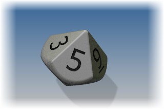
This time I chose to create a model of the 10 sided die.

The finished 10 sided die
To add a little more fun, here's a new trick I'm trying.  Embedding a dwf of the die inside the webpage!  Try giving it a rotate and pan!


When I started to look at building this die, I found this model easier to create that the 20 sided die.  But even though I thought it was a little easier to create, I also found it had it's own set of challenges.  It took me a few tries before I got a result I was happy with.

I ended up using two lofts, and trimming the plane where they met to get the result.  I then added fillets to clean up the edges and get the result I was looking for. 

But, without further adieu, here are the steps! 

  • The first step was to create a single line on a sketch plane.  I'm going to use each end of the line as one end of two lofts I'm going to create. I also made sure that the midpoint of the line was placed at the origin.  This will let me use the origin workplanes to create sketches in my next steps.

The first line defining the top and bottom of the die.

  • Next I created a sketch on my origin plane, added a pentagon, and dimensioned it.

The additional sketch added.
  • Now I'm ready to loft between the two.  I choose the loft tool, and loft between the pentagon and one of the line's endpoints. 

Creating the loft

The finished loft

  • Before I started modeling, I looked at an image of a real die, I realized that the upper and lower halves were offset, so I couldn't use the same loft.  So I created a second pentagon, rotated from the first, and repeated the steps above.

Creating the second loft.  Notice how it's offset from the first.
  • Now I was left with sharp overhangs on the die that weren't going to work at all. It was time to clean those up!


The die before cleaning up.  Not pretty at all!
  • To clean up the sharp corners, I created a sketch where the two pentagons meet.  (Note I used slice graphics, just like in my previous post here).  I sketched a circle, then used Extrude with the intersect option remove the sharp corners.
Creating the feature for the Extrude commad


Extruding using the intersect option
  • Now the hard work is done.  All that is left is the tedious work of adding the numbers.

Adding the numbers to the die
  • And finally, using the fillet tool to round off the sharp corners!
All done!

 A quick rendering, in Autodesk Showcase, and I'm ready to go!


 Just like with the 20 sided die, below are two links where you can download the model if you'd like.  And just like before, all I ask is that you give a me a little nod if you decide to use the model.  Enjoy!
Download from Autodesk 360 

Download from GrabCAD (login required)

Friday, November 09, 2012

All for Fun Again - Modeling the 12 Sided Die

"Death and dice level all distinction."
Samuel Foote 

Today is Friday, and you might have noticed that in the last couple of weeks I've been challenging myself by created 3D models of gaming dice.

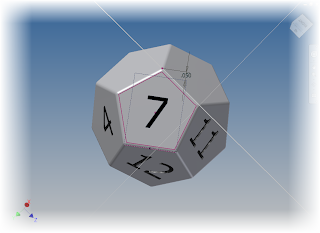
So far, I've created to 20 sided die, the 10 sided die, and now I've added the 12 sided die.

P.S. the view below is an embedded 3D DWF that can be panned, zoomed, & rotated!


This one ended up being the most challenging so far, at least until I got the construction method down.  Once I had that figured out, it wasn't hard, just time consuming.


So here are the steps I used to build it!

The first thing I did was locate directions on how to build the shape that eventually becomes the die.  It's called a dodecahedron, and like the 20 sided die, I found it's construction on Wikipedia.  It was composed of using a rectangle, and points placed at certain coordinates in space.  The Wikipedia article gave me these coordinates.

The construction for the die
  • I took this information, and using a rectangle extruded as a surface, and three rectangles, created the required points.  The points are the verticies of each figure. 

The skeleton that starts it all


  • Next, comes the process of creating the faces.  I used a workplane between three point on the skeleton.  Created a 2D sketch, and started projecting geometry and sketching the boundaries of the face.  This takes some time and patience.


Getting started with the construction

Further along in the construction.  I turned off the workplane visibility to try to make the image a little more clear.

  • Once the skeleton was finished, I went through and created boundary patches that filled in each face of the die.

Now surfaces close up the shape
  • With the surfaces created, now I used the "Stitch" command to seal surfaces up, converting them to a solid.

The converted solid
  • My next step was to add a fillet to break all the edges.

The fillet added to the die.

  •  Finally, the long, long process of adding 12 sets of numbers to the die.  It's not difficult, but like most things creating these dies, it takes time, it's an exercise in more time, and more patience.

The sketches in the process of getting created.

  • Finish the text and I'm done
  • Finally, a drop into Showcase to give it a little flair!


So there it is, one more die out of the way.  I still plan on doing the rest, 8 sided, 4 sided, and 6 sided (which is easy). 

On a final note, if you want to download the models.  You find them on GrabCAD and Autodesk 360.
Click here for Autodesk 360 Download
Click here for GrabCAD Download

Sunday, May 08, 2016

Learning Fusion 360 - Building a 20 Sided Die

Many, many moons ago, a friend of mine asked me to model dice for a local gaming store, Dicehouse Games.  The trickiest of these was the 20 sided die, like I have pictured here.


Feel free to check out that post here,  I'm going to focus on my Fusion 360 experience here.  I found the steps were actually very similar.

Consider it a little bit of a musing about how my previous experience in Inventor compared to creating the die in Fusion 360.

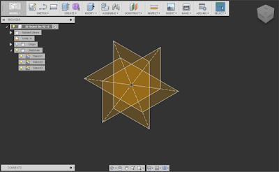
The initial steps were the same, I created three rectangle on the XY, XZ, and YZ planes with a ratio of 1:1.618.  Just like before, I referenced this Wikipedia article here.

You may hear these referred to as the "Golden Rectangle".

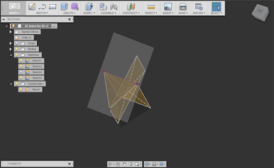
The very skeleton of the 20 sided die.  The golden rectangles with a ratio of 1:1.618

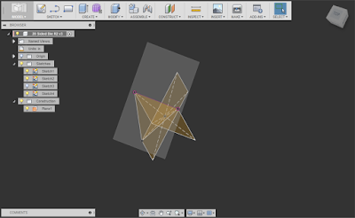
Next, came the "how does Fusion 360 do it?" moment.  That meant building some workplanes using the "Plane Through Three Points" tool, and creating a sketch on that workplane.

I sketched three lines, using the three points of the rectangles as shown below.

The three point workplane with a sketch created on it.  One of the "Golden Rectangles has its visibility turned off to reduce "cluttter". 
To keep my process as simple as possible, I also created a boundary patch from the triangle.  It makes it easier to use turn off the visibility of these objects when things get a little cluttered.

The same model, with the boundary  patch added. 

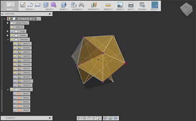
Now there's a lot of "rinse and repeat" type of steps.  More 3 point workplanes, more sketches, and more lines defining triangles.

More boundary patches begin to define the "skin' of the die. 
But as I added more patches, I realized I could tweak my process a little bit, and make the operation go a little more easily.

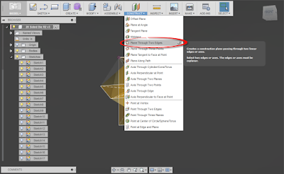
I realized, I had enough patches where instead of using the Plane Through Three Points Workplane tool, I could use the "Plane Through 2 Edges Tool".  This was because I now had adjacent patch edges I could use to help me .

Fewer picks, faster process.

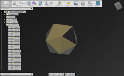
Once you have a few patches created, you can make better progress! 

There was more repeating of the now modified steps.  More sketches, more patches, until at long last, I had a complete skeleton of the die made with workplanes, surfaces, and boundary patches.

The die skinned with twenty different patches. 
Now what's left to do is to to make a solid out of it, using the "Stitch" tool.   This seals the 20 surfaces into a solid.  I now have a twenty sided solid!

The now stitched die!  Note I changed my background color to make the now solid die a little more clear. 

After this, comes the long process of adding numbers.  This will take a while.  There's no real getting around that.

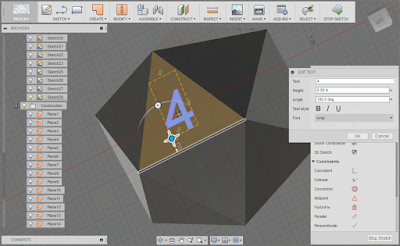
Sketching in text.  Fusion 360's drag and rotation tools really helped this process. 
There was a lot of sketch, extrusion, sketch extrusion, going on here.  But finally the whole die was modeled!

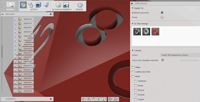
Now, I added a little color.  I had experimented with orange, but went for red this time.

Dragging color onto the die using the render environment. 

After quite a bit of dragging, the colors are all done!

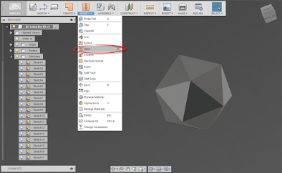
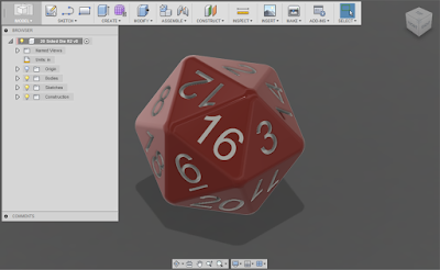
After adding fillets to smooth the rough edges, and the die is done!

The die completed! 
So after that exercise, what did I learn, and like about this exercise?

1) Neat little workflow in sketching! 
When you start a sketching tool, and there isn't an active sketch, Fusion will start a sketch for you.  Thanks for the help with that!!

2) Drag and drop. I like it.  That is all. 
Fusion's push pull and rotation tools on the "drag and drop functionality really came in handy.  It was nice to rotate and move text by dragging with the grips.  It made that tedious task go a little faster.

3) Keep an open mind, you might need to try a model a couple of times to get it right.
I started one model, then threw it away when I realized I wasn't making it as efficiently as I could.  I get we can't all do that, but make sure to look for the lessons to improve your flow for the next time.

4) Take the lessons you learned from one program, but don't take them too seriously.
We've all heard the frustrated user say "This program doesn't do it like MYFAVORITECAD!"  Well, no. It's not MYFAVORITE CAD.  Maybe it doesn't better, maybe not.  But at least be open to the changes before you dismiss them!


So my adventures in Fusion 360 continue.  I'm enjoying them, and I'll continue looking for ways to improve my skills set.

And if you'd like to take a look at this model yourself.  Here's a link to download it.  That's right.  Yours for the taking, enjoy!

I'm considering writing some posts describing how I built the die in a little more detail.  If you're interested, feel free to throw in a comment!


Thursday, November 15, 2012

And Yet Again, All for Fun - The 8 Sided Die

"DIE, n. The singular of "dice." We seldom hear the word, because there is a prohibitory proverb, "Never say die.""
Ambrose Bierce

This seems to have become a Friday series.  The last few weeks I've placed a model of a gaming die on my blog, and talked about the process I went through making each one.

It stared out as a project for a website (they're the banner on the Dicehouse Games website).

Then I stated being asked if I would supply the models.  So I started making them available for download and describing the steps I used here.

So far, I've created posts for the 20 sided die, the 10 sided die, and the 12 sided die.  Now, I add the 8 sided die. 


The completed die

Here's the completed die as an embedded 3D dwf file.  Click and drag to give it a spin!


This one is a pretty simple model to create, at least when compared to the others!

  • First, I sketched a square on an origin workplane.  In my case, I chose the XZ workplane. 

The first step that starts it all


Next, I bisected the square with a line, on a plane perpendicular to the sketch I first used.  It's worth noting that I later on realized that I only needed half the line, but I left the die as I started it.

Added the perpendicular line.  I later realized I didn't need the whole line

Now, it's time to create a loft from the square, to one of the line's endpoints.

Creating half of the die

With half the die completed, I used the Mirror command to create the other half of the die.

Using the Mirror command to create the other half of the die

That takes care of the heavy lifting!  Now, I just add a fillet to break the sharp edges.  Notice that I used the "All Round" option to select all the external edges at once.

Breaking the sharp edge

Finally, the long tedious task of adding the number.  This hasn't changed, its just a matter of creating a sketch with the number, and extruding it a shallow distance.  At least there are fewer now!

The process of adding the numbers


And because I can, here's the quick rendering in Autodesk Showcase.

And a rendering to make it look cool!

P.S. If you're wondering why I didn't loft from the line's endpoint, to the square, to the other endpoint, here's what happened when I tried.


Needless to say, this wouldn't have made a very good die.  So I changed my approach, and used the Mirror command instead.  But now you know why I created the line the way I did.  It's a vestige of an aborted work process!

Doh!  Not what I wanted!

And of course, here are the links to download the files.
Click here for the Autodesk 360 link

Click here for the GrabCAD link

Enjoy!  I hope to see some of you at Autodesk University 2012!


Tuesday, December 04, 2012

Wrapping up a Little Fun - Modeling the Six Sided Die

"It means that I, like God, do not play with dice and do not believe in coincidence."
"V" From V for Vendetta

Afrer modeling nearly all of the gaming dice, (20 sided, 12 sided, 10 sided, 8 sided, and 4 sided), I decided to complete the set with the 6 sided.

Originally, I was going to post this particular die as a bit of a joke.  Draw a square, extrude it into a cube, break the edges and slap some numbers on it.  How hard could it be?

Examples of 6 sided die (courtesy Wikipedia)

Could you believe I found a way to complicate it?  And find a use for a new trick in the process?

I'll share the trick at the end of the blog.  First, I'll start out with the steps I used.  Which let's face it, aren't that difficult.  But there might still be a trick or two to use.

1) First, I created the cube.  Since I used Autodesk Inventor 2013, I used the "Box" primitive that was added in this release.

Using the "Box" primitive to create the cube for the die.


2) Next, I added fillets to break the sharp edges.  I used the "All Rounds" option to get every edge.

Adding fillets to break the edges


3) Finally, I added the numbers to each side of the die.

Finally, adding the numbers!


And that's it.  The die is finished.

But there's an epilogue to this exercise.  Looking at the die, I didn't like the way it looked. The edges were too crisp and clean.  It didn't look like a real die would.  I decided I wanted the vertices of the die to look more rounded than the rest of the die.

Looking carefully the rounded corners can be seen (image courtesy Wikpedia)

Thg "too crisp" corner shown.  I'm using the "shaded with edges" setting to show the corner more clearly.

So how did I go about changing that?  I edited the fillet, created in step 2, and on the "setbacks" tab, I chose each corner of the die, and changed the setback until I liked the result (I used .1875 in my case). 

I found it gave a much more eye pleasing result than the tight corners I initially had.


Changing the setback
The completed die with setback
Ironically, I can't think of another time I've really used the setback setting.  It's possible that I might have used it somehwhere, but I can't recall one. 

I guess it just goes to show that one should never say "I'll never use that tool!"

And naturally, I have to add a rendering from Autodesk Showcase, just because!

And one for the show!


And if you want do download the model here you go!

Click here to download from Autodesk 360 (no login required)

Click here to download from GrabCAD (login required)

I hope you find this model an interesting diversion!